Contents
Introduction
Author: Movania Muhammad Mobeen
Hello readers, In this article, we will learn how to port the 8th tutorial on printing fonts in OpenGL 3.3. We saw in the last tutorial how to use camera matrices to handle transformations for us in OpenGL 3.3 and above. In this article, we focus on how to print text on screen to display properties to the user. While the original tutorial used display lists, they have been deprecated in OpenGL3.0 and removed in OpenGL 3.3 core profile. Hence, we cannot use the display list. Now in OpenGL 3.3 and above, we have to use shaders to achieve font printing.
Handling fonts in OpenGL 3.3
There are two ways to handle fonts in OpenGL3.3. We use the texture mapped fonts We use the true type fonts by using the freetype library We opted for the first method which involves rendering a font on an image and then rendering a sub-image of the letter from the image on the geometry displayed orthogonally to the viewer. To make our work easier, we have defined a new C++ class to handle texture mapped fonts. We call this class TextureMappedFont. The interface of the class is defined as follows:
	class TextureMappedFont
	{
	public:
	    TextureMappedFont(void);
  	    TextureMappedFont(const string& fontTexture, float fontSize=16.0f);
	    ~TextureMappedFont(void);

	    bool Init();
	    void DrawString(float x, float y, const string& string, matrix_4x4_type current, bool selected=false );

	private:
	    GLuint _textureID, _vaoID;

	    GLuint _texCoordBuffer;
	    GLuint _vertexBuffer;
	    float _fontSize;

	    matrix_4x4_type P; //orthographic projection matrix
	    GLSLShader _shader;
	};
The constructor accepts the name of the font texture image to load the fonts from. The next parameter is the size of the font. We give it a default value of 16. We then define utility functions. Once the texturemappedfont constructor is called, it automatically calls the init function. This constructor is responsible for loading the font texture image. It is also responsible for loading, compiling and linking our font shader. After this, it calls the init function which handles the VBO for storing the vertices for geometry on which the font will be pasted. The vertices are bound first. These calls should be easy to understand now (if not you may refer to earlier tutorials for details):
	bool TextureMappedFont::Init()
	{
	    float vertices [] = {
	        0.0f, 0.0f,
	        _fontSize, 0.0f,
	        _fontSize, _fontSize,
	        0.0f, _fontSize
	    };

	    GL_CHECK_ERRORS

	    glGenVertexArrays(1, &_vaoID);
	    glBindVertexArray(_vaoID);
	    glGenBuffers(1, &_vertexBuffer);
	    glBindBuffer(GL_ARRAY_BUFFER, _vertexBuffer);
	    glBufferData(GL_ARRAY_BUFFER, sizeof(GLfloat) * 8, &vertices[0], GL_STATIC_DRAW);
	    glEnableVertexAttribArray(_shader["vVertex"]);
	    glVertexAttribPointer(_shader["vVertex"], 2, GL_FLOAT, GL_FALSE, 0, 0);
Once the vertex positions are specified, we specify the texture coordinates as follows:
	//Just initialize with something for now, the tex coords are updated
	//for each character printed
	float texCoords [] = {
	    0.0f, 0.0f,
	    0.0f, 0.0f,
	    0.0f, 0.0f,
	    0.0f, 0.0f
	};

	glGenBuffers(1, &_texCoordBuffer);
	glBindBuffer(GL_ARRAY_BUFFER, _texCoordBuffer);
	glBufferData(GL_ARRAY_BUFFER, sizeof(GLfloat) * 8, &texCoords[0], GL_DYNAMIC_DRAW);
	glEnableVertexAttribArray(_shader["vTexCoord"]);
	glVertexAttribPointer(_shader["vTexCoord"], 2, GL_FLOAT, GL_FALSE, 0, 0);
One thing that we have changed here is the usage flags. For the texture coordinates, we have specified GL_DYNAMIC_DRAW usage flag which tells the OpenGL driver to keep the texture coordinate buffer in a fast access memory since we will be chaging its contents again and again. This is becase we will be mapping different letter to the geometry as we will see later. In the end of the init function, we issue a call to the Orthographic function that is similar to the fixed function glOrtho function:
	//set the orthographic projection matrix
	Orthographic(0.f, float(screen_width), 0.f , float(screen_height),-1.f,1.f, P);
This function generates the orthographic projection matrix for us so that we may render the font perpendicular to the viewer. We will dissect this function in a later section.
Drawing text
To draw text, the texturemappedfont class defines a function called DrawString. The first two parameters are the x and y location (in screen space) where the text will be drawn. The third parameter is the string to draw. The fourth parameter is the current modelview matrix being used at the time of the DrawSting call. The last parameter is a boolean flag used to indicate whether the current string is selected. This is used to display the string in a different color if it is selected. This method first disable's the depth test to make sure that the text is rendered on top of any other world geometry. Before disabling though, we store the current depth test state so that we may undo it when we are done rendering our font:
	GLint test[1];
	glGetIntegerv(GL_DEPTH_TEST, test);
	glDisable(GL_DEPTH_TEST);
Next we use our shader:
_shader.Use();
Next we bind our font texture and then generate the translation matrix to position the text:
	matrix_4x4_type translate, MV, oldMV, MVP;
	MatrIdentity_4x4(MV);
	MatrIdentity_4x4(MVP);
	MatrIdentity_4x4(translate);
	//Position our text
	translate[3][0]=x;
	translate[3][1]=y;
We multiply the translate matrix to the current matrix to get the modelview matrix (MV):
MatrMul_4x4_4x4(translate, current_matrix, MV);
Next, we loop through all of the letters in the string and dynamically generate the texture coordinates in order to display the letters on the geometry. To enable this, we first bind our VAO and then run a loop and in each loop generate a new set of texture coordinates as follows:
	MatrMul_4x4_4x4(MV, P, MVP);
	const float oneOverSixteen = 1.0f / 16.0f;
	int ch = int(str[i]);
	float xPos = float(ch % 16) * oneOverSixteen;
	float yPos = float(ch / 16) * oneOverSixteen;

	texCoords[0] = xPos;
	texCoords[1] = 1.0f - yPos - oneOverSixteen;

	texCoords[2] = xPos + oneOverSixteen;
	texCoords[3] = 1.0f - yPos - oneOverSixteen;

	texCoords[4] = xPos + oneOverSixteen;
	texCoords[5] = 1.0f - yPos - 0.001f;

	texCoords[6] = xPos;
	texCoords[7] = 1.0f - yPos - 0.001f;
Next, we bind our VBOs and issue our DrawArrays call to draw the geometry:
	glBindBuffer(GL_ARRAY_BUFFER, _texCoordBuffer);
	glBufferSubData(GL_ARRAY_BUFFER, 0, sizeof(float) * 8, &texCoords[0]);

	glUniformMatrix4fv(_shader("MVP"), 1, GL_FALSE, &MVP[0][0]);
	glUniform1i(_shader("selected"), sel);

	GL_CHECK_ERRORS

	glDrawArrays(GL_TRIANGLE_FAN, 0, 4);
We also pass the selection flag to the shader by setting the appropriate uniform so that we may color the selected text differently. Finally, we modify the X coordinate of the translation matrix to position the next letter and obtain a new modelview (MV) matrix:
	MatrCopy_4x4(oldMV,MV);
	matrix_4x4_type t2;
	MatrIdentity_4x4(t2);
	t2[3][0]=_fontSize * 0.8f;
	MatrMul_4x4_4x4(t2, oldMV, MV);
After the loop, we unbind our VAO and then unuse our shader and reset the depth test OpenGL state:
	glBindVertexArray(0);
	GL_CHECK_ERRORS

	_shader.UnUse();

	GL_CHECK_ERRORS

	if(test[0])
	   glEnable(GL_DEPTH_TEST);
Texture mapping shader
The vertex shader is exactly same as the previous tutorials. The fragment shader however is slightly modified:
	#version 330
	precision highp float;
	uniform sampler2D texture0;
	in vec2 TexCoord;
	out vec4 vFragColor;
	uniform bool selected;

	void main(void) {
	   vec4 col=selected?vec4(1,0,0,1):vec4(1);
	   vFragColor = texture(texture0, TexCoord.st)*col;
   	   if (vFragColor.rgb == vec3(0.0, 0.0, 0.0)) {
   	      discard;
	   }
	}
Here we have added a boolean flag to see whether the current string is selected. If it is selected, we set the col variable to red color (vec4(1,0,0,1)). Otherwise we color it white. Next, we sample the texture (font texture) with the interpolated texture coordinates (TexCoord.st). The result of this is multiplied by the col variable to color it red if it is selected otherwise color it as white. One more thing interesting here is the removal of black color. If we find a color having the rgb value of vec3(0,0,0) i.e. black color, we discard that fragment. The discard keyword allows us to remove the current fragment from the current graphics pipeline skipping all of the later depth/stencil/alpha test /raster operations.
Using the texturemappedfont class
The usage of this class is pretty simple. We just need to include the relevant header:
#include "texturemappedfont.h"
Then, we create instances of the class:
	//in global scope
	TextureMappedFont* font1;
	TextureMappedFont* font2;
	//in init code
	font1=new TextureMappedFont("font1.bmp");
	font2=new TextureMappedFont("font2.bmp");
Finally, when we need to draw the text, we simply call the DrawSring method like this:
	//draw the font
	font2->DrawString(cs_pos[0], cs_pos[1], object[i].name, camera.matrix, (i==obj_control) );
	// Print object information
	sprintf(l_string,"Object selected: %s",object[obj_control].name);
	font1->DrawString(0,screen_height-20,l_string, camera.matrix);
	sprintf(l_string,"Position: x=%.1f y=%.1f z=%.1f",object[obj_control].matrix[3][0], object[obj_control].matrix[3][1], object[obj_control].matrix[3][2]);
	font1->DrawString(0,screen_height-40, l_string, camera.matrix);
Obtaining the screen space position of the mesh to display text on it
In the original tutorial, the feedback buffer mode of OpenGL was used to get the screen space position of the OpenGL meshes. In OpenGL 3.3, this has to be done by the programmer himself. The calculation for this is pretty trivial. We know that the combined modelview matrix (MVP) brings the coordinates of the object from the objects model space to view/eye/camera space. We know that the centroid of our object is at the object space position op=(0,0,0,1). We first multiply the point (op) with the modelview projection matrix (MVP) to get the clip space position of the point (op) we call (cp):
	float op[4]={0,0,0,1};
	float cp[4]={0};
	#ifdef USE_GLM
	   MatrMul_GLM(cp, glm::value_ptr(MVP), op);
	#else
  	   MatrMul_Vec(cp, MVP,  op);
	#endif
The clip space is where the coordinates are from -1 to 1 in all three axes. Next comes the perspective division where we divide all of the three coordinates (x,y and z) of the clip space point by the w coordinate (the fourth coordinate). This gives us the normalized device coordiantes (NDC):
	float ndc[3] = {0};
	ndc[0] = cp[0]/cp[3];  //in range [-1 to 1]
	ndc[1] = cp[1]/cp[3];  //in range [-1 to 1]
	ndc[2] = cp[2]/cp[3];  //in range [-1 to 1]
The normalized device coordinates (NDC) are then mutiplied by half of the screen dimension and offset by half of the screen dimension to get the screen space position of the given point:
	float sp[2]={0};
	sp[0] = width/2.0  + ndc[0]*width/2.0; 				//in range [0 to  width]
	sp[1] = height/2.0 + ndc[1]*height/2.0; 			//in range [0 to height]
	sp[2] = ndc[2]*(depthRange[1]-depthRange[0]) + depthRange[0];	//in range [depthRange[0] to depthRange[1]]
The sp[0] is the x coordinate in screen space and sp[1] is the y coordinate. The screen space z value (sp[2]) is based on the current depth range. This range is usually in the [0 to 1] range and can be queried by calling:
	//get the depth range
	GLfloat depthRange[2];
	glGetFloatv(GL_DEPTH_RANGE, depthRange);
The ndc[2] value is multiplied by {(depthRange[1]-depthRange[0]) + depthRange[0]} so that when ndc[2] is 0, we have the depthRange[0] and when it is 1, we have depthRange[1]. This is the basic linear interpolation formula. For rendering of text however, we are only interested in the screen sapce x and y coordinates. We can now render the text on this location by calling our font's DrawString function:
	//draw the font
	font2->DrawString(sp[0], sp[1], object[i].name, camera.matrix, (i==obj_control) );
As you might know, the last parameter is the selection flag which tells us whether the current object is selected. This is true if the object currently controlled (obj_control) == the current loop variable i.
Dissecting the orthographic projection function
Here we will see what the Orhtographic function does to obtain the orthographic projection matrix. The function is defined as follows:
	void Orthographic(float left, float right, float bottom, float top, float nearV, float farV, matrix_4x4_type matrix) {
	    MatrIdentity_4x4(matrix);
	    matrix[0][0] = 2.0f/(right-left);
	    matrix[1][1] = 2.0f/(top-bottom);
	    matrix[2][2] = -2.0f/(farV-nearV);
	    matrix[3][0] = - (right+left)/(right-left);
	    matrix[3][1] = - (top+bottom)/(top-bottom);
	    matrix[3][2] = - (farV+nearV)/(farV-nearV);
	}
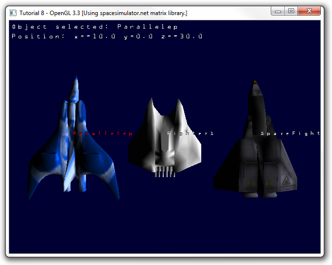
Like before, if you want to know why the elements are the ones given here, we would ask you to consult a basic computer graphics book or the official OpenGL programming guide. Running the code gives us the following output. You may press the 'w','a','s','d' keys along with several other keys to transform the camera and see the result:
SOURCE CODE
The Source Code of this lesson can be downloaded from the Tutorials Main Page