Contents
INTRODUCTION
Original Author: Damiano Vitulli
Translation by: Click here
First, it's necessary to explain the basic concept... what is a 3d engine?
The answer is relatively simple:
A 3d engine is a whole of structures, functions and algorithms used to visualize, after many calculations and transformations, 3d objects on a 2d screen.
The main sections of a 3d engine are:
- The acquisition of the objects' data in structures.
- The transformations to position the objects in the world.
- Rendering the scene on the 2d screen.
This is why we are here so... let's go to work!
In this lesson, we will study how to define the main structures needed to draw a 3d object.
THE VERTICES
Suppose you have an object and want to show it on a 2d screen. In order to do this, it's necessary to obtain information about its structure. How can we do this?
First, we define some key points: the vertices of the object. Every vertex is composed of three coordinates x, y, z. Every coordinate must be expressed through a FLOAT or DOUBLE variable, this is because we always need the best resolution to render the scene.
To define a vertex in C, we use a structure composed of three variables x, y, z.
typedef struct {
    float x,y,z;
} vertex_type;
It's very important to keep in mind that all of the calculations that deal with the positioning and the rotation of the object are applied to the vertices, since they are the units that make up the basic structure. The second structure, in terms of importance, is the polygon.
THE POLYGONS
The polygons are the faces of the object and are composed from N vertices. In most 3d engines polygons are composed of 3 vertices hence we will use this rule as well.
Using our vertex_type structure, we can define a polygon structure that contains 3 vertices:
typedef struct {
    vertex_type a,b,c;
} polygon_type;
We will also declare a polygon_type array variable that will be filled with all the polygons that constitute the object.
#define MAX_POLYGONS 2000
polygon_type polygon[MAX_POLYGONS];
But... look out! Our definition assigns 3 vertices to every polygon and these vertices are not shared with the other polygons. Actually, if we reflect a while, we are going to see that every polygon of an object does in fact shares its sides, and also its vertices, with other polygons. So we have made a mistake! Well, it is not really a mistake, but we have increased, considerably, the real number of vertices on the scene well beyond what is necessary. We have already said the engine will use the vertices to carry out most of its calculations so we should really find another method to define the polygons.
We could create a list of vertices that will hold all of the vertices of the entire object. Then, in order to define the polygons, we will use a sort of referencing scheme to "point" to the vertices of that list.
We now declare an array variable of type vertex_type that will hold MAX_VERTICES vertices.
#define MAX_VERTICES 2000
vertex_type vertex[MAX_VERTICES];
The polygon structure will not contain the vertices any more but only 3 numbers that will point to 3 elements of the vertices list. In this way more polygons can point to the same vertex. This greatly optimizes the design of the engine.
typedef struct {
    int a,b,c;
} polygon_type;
THE OBJECT
We do a little bit of cleanup here and organize the previous definitions in a structure that we will call obj_type.
typedef struct {
    vertex_type vertex[MAX_VERTICES];
    polygon_type polygon[MAX_POLYGONS];
} obj_type,*obj_type_ptr;
That's only a basic definition. In the future, we will add more fields that will identify the position, rotation and state of the object. At this point we can declare the object variable and fill the vertices list:
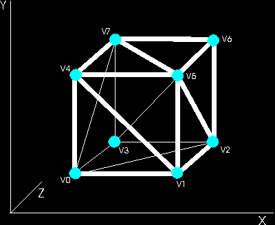
obj_type obj;
obj.vertex[0].x=0; obj.vertex[0].y=0; obj.vertex[0].z=0; //vertex v0
obj.vertex[1].x=1; obj.vertex[1].y=0; obj.vertex[1].z=0; //vertex v1
obj.vertex[2].x=1; obj.vertex[2].y=0; obj.vertex[2].z=1; //vertex v2
obj.vertex[3].x=0; obj.vertex[3].y=0; obj.vertex[3].z=1; //vertex v3
obj.vertex[4].x=0; obj.vertex[4].y=1; obj.vertex[4].z=0; //vertex v4
obj.vertex[5].x=1; obj.vertex[5].y=1; obj.vertex[5].z=0; //vertex v5
obj.vertex[6].x=1; obj.vertex[6].y=1; obj.vertex[6].z=1; //vertex v6
obj.vertex[7].x=0; obj.vertex[7].y=1; obj.vertex[7].z=1; //vertex v7
Now the problem is on how to subdivide our cube in triangles. The answer is simple: every face of the cube is a square composed of two adjacent triangles. So our cube will be composed of 12 polygons (triangles) and 8 vertices.
The list of polygons must be filled like so:
obj.polygon[0].a=0;  obj.polygon[0].b=1;  obj.polygon[0].c=4;  //polygon v0,v1,v4
obj.polygon[1].a=1;  obj.polygon[1].b=5;  obj.polygon[1].c=4;  //polygon v1,v5,v4
obj.polygon[2].a=1;  obj.polygon[2].b=2;  obj.polygon[2].c=5;  //polygon v1,v2,v5
obj.polygon[3].a=2;  obj.polygon[3].b=6;  obj.polygon[3].c=5;  //polygon v2,v6,v5
obj.polygon[4].a=2;  obj.polygon[4].b=3;  obj.polygon[4].c=6;  //polygon v2,v3,v6
obj.polygon[5].a=3;  obj.polygon[5].b=7;  obj.polygon[5].c=6;  //polygon v3,v7,v6
obj.polygon[6].a=3;  obj.polygon[6].b=0;  obj.polygon[6].c=7;  //polygon v3,v0,v7
obj.polygon[7].a=0;  obj.polygon[7].b=4;  obj.polygon[7].c=7;  //polygon v0,v4,v7
obj.polygon[8].a=4;  obj.polygon[8].b=5;  obj.polygon[8].c=7;  //polygon v4,v5,v7
obj.polygon[9].a=5;  obj.polygon[9].b=6;  obj.polygon[9].c=7;  //polygon v5,v6,v7
obj.polygon[10].a=3; obj.polygon[10].b=2; obj.polygon[10].c=0; //polygon v3,v2,v0
obj.polygon[11].a=2; obj.polygon[11].b=1; obj.polygon[11].c=0; //polygon v2,v1,v0
You must keep in mind that in order to define the polygons properly it is necessary to always use the same clockwise or counter-clockwise direction for all the polygons on the scene. We will see in the next tutorial, how the direction is used to control weather the polygon is visible or not. So pay close attention to the way you define the polygons or many of them will not be visible.
We will use the counter-clockwise method (for example the first polygon is defined by v0,v1,v4 or v1,v4,v0 or v4,v0,v1 and not v1,v0,v4 or v0,v4,v1 or v4,v1,v0).
ANOTHER MORE ELEGANT WAY TO DEFINE OUR OBJECT
In C/C++ we can fill the obj_type structure using this more elegant way:
obj_type cube =
{
    {
        -10,-10, 10, //vertex v0
         10,-10, 10, //vertex v1
         10,-10,-10, //vertex v2
        -10,-10,-10, //vertex v3
        -10, 10, 10, //vertex v4
         10, 10, 10, //vertex v5
         10, 10,-10, //vertex v6
        -10, 10,-10  //vertex v7
    },
    {
        0, 1, 4, //polygon v0,v1,v4
        1, 5, 4, //polygon v1,v5,v4
        1, 2, 5, //polygon v1,v2,v5
        2, 6, 5, //polygon v2,v6,v5
        2, 3, 6, //polygon v2,v3,v6
        3, 7, 6, //polygon v3,v7,v6
        3, 0, 7, //polygon v3,v0,v7
        0, 4, 7, //polygon v0,v4,v7
        4, 5, 7, //polygon v4,v5,v7
        5, 6, 7, //polygon v5,v6,v7
        3, 2, 0, //polygon v3,v2,v0
        2, 1, 0, //polygon v2,v1,v0
    }
};
You can also see that we changed the vertices coordinates from 0,1 to 10,-10. This is intentional, Infact, we need to have the center of the object at 0,0 (we will understand why in the next tutorial). Our object is also 20 times bigger (just to easily manage coordinates).
CONCLUSIONS
That's all for this lesson. In the next one, we will begin to use OpenGL to show our cube on the screen.
SOURCE CODE
The Source Code of this lesson can be downloaded from the Tutorials Main Page